

Build a simple rocket launcher out of PVC pipe and an electric lawn sprinkler valve. It launches paper rockets a shocking 250 feet up. This is project is from Make: 15, page 103. We have made some slight modifications to the parts and the process.
Link for pdf of instructions.
MATERIALS:
One 2" PVC pipe, 10" length
One 3/4" PVC pipe, 3" length
One 3/4" PVC pipe, 4" length
One 1/2" PVC pipe, 16" length
Two 3/4" PVC pipe, 16" length
One 1/2" PVC pipe, 13" length
One 2" spig x 1/2" Fipt reducer bushing [PVC Fittings Direct part 438-247, $1.75]
One 2" PVC tee, slip x slip x slip [PVC Fittings Direct part 401-020, $1.90]
One 1/2" male x 1/8" fem. brass bushing NPTF [McMaster Carr part 50785K64, $2.34]
One 3/16" brass hose barb x 1/8" male NPTF [McMaster Carr part 5346K11, $0.80 ea.]
One 2" PVC cap, slip [PVC Fittings Direct part 447-020, $0.84]
Two 3/4" male adapter, mipt x slip [PVC Fittings Direct part 436-007, $0.26 ea.]
One 3/4" spig x 1/2" slip reducer bushing [PVC Fittings Direct part 437-101, $0.26]
One 2" spig x 3/4" slip reducer bushing [PVC Fittings Direct part 437-248, $1.23]
Two 3/4" caps, slip [PVC Fittings Direct part 447-007, $0.26 ea.]
One 3/4" inline 24V sprinkler valve [Amazon.com part B00004S1V2, $13.55]
One 5/16" OD x 3/16" ID flex. tubing, 6' [McMaster Carr part 5231K325, $2.70 ]
Two pinch hose clamps, 9/32" to 23/64" [McMaster Carr part 6541K35, $8.00 for 25]
One tire valve (Schrader valve)
One SPST momentary pushbutton switch N.O. [All Electronics part PB-179, $0.90]
Two 14" zip ties
Two 11" zip ties
One 22 AVG red/black zip cord, 10' length [All Electronics part WRB-22, $1.20]
Two 9V battery connectors, I-type [All Electronics part BST-51, $0.50 ea.]
Two 9V batteries
Duct tape
TOOLS:
PVC pipe primer (e.g., Oatey 307560)
PVC pipe cement (e.g., Oatey 31013)
Latex gloves
Duct tape
Electrical tape
Bicycle pump
Rubber mallet
Drill and bits: 3/8", 5/16", 3/16", and 5/32"
Small screwdriver
Soldering iron and solder
Adjustable wrench
Channel lock pliers
Wire stripper
Vice Grips (optional)
Pinch clamp pincer (optional)
Please note: Only schedule 40 PVC should be used
STEP 1. ASSEMBLE THE PRESSURE CHAMBER
Read the instructions on the PVC primer and PVC cement cans. Always use the PVC primer before using the PVC cement. Where gloves when priming and cementing PVC pipe.
Materials for step 1:
One 2" spig x 1/2" Fipt reducer bushing
One 2" PVC tee, slip x slip x slip
One 1/2" male x 1/8" female brass bushing
One 3/16" brass hose barb x 1/8" male NPTF
One 10" long 2" PVC pipe
One 2" PVC cap, slip connection
Tools for step 1:
Latex gloves
PVC pipe primer (e.g., Oatey 307560)
PVC pipe cement (e.g., Oatey 31013)
Rubber mallet
Teflon tape
Channel lock pliers
Adjustable wrench
Instructions:
Find the 2" spig x 1/2" Fipt reducer bushing and the 2" PVC tee, slip x slip x slip, which are shown the below.

Prime and cement the two parts together.

Apply teflon tape to the threads of the 1/2" male x 1/8" female brass bushing.

Hold the reducer bushing with your channel-lock pliers and insert and tighten the 1/2" male x 1/8" fem. brass bushing, as shown below.

Screw the 3/16" brass hose barb x 1/8" male into the into the 1/2" male x 1/8" fem. brass bushing, as shown below. (No need to use teflon tape on this brass connection.)

Find the 10" long 2" PVC pipe and the 2" PVC cap, slip connection, which are shown below.

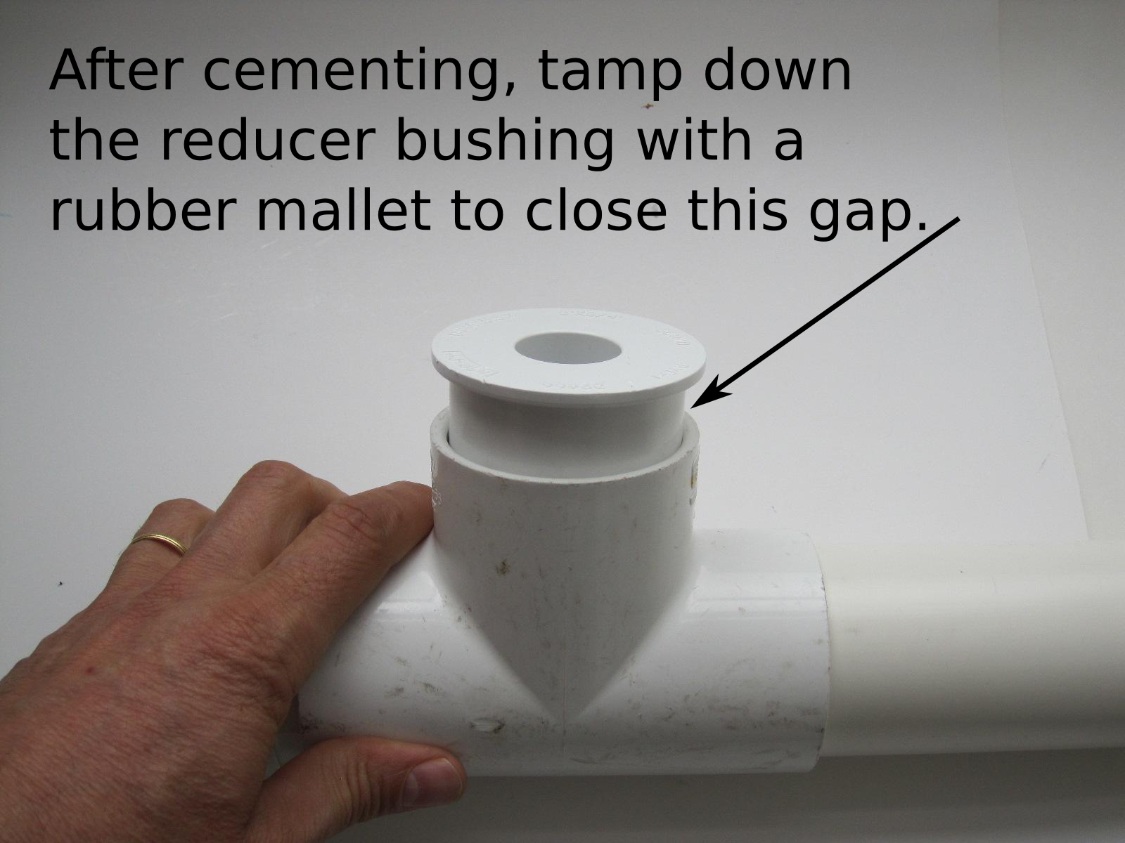
Prime and cement the two parts together, as shown below. Tamp down the cap with a rubber mallet.

Prime and cement the 10" long 2" PVC pipe to the 2" PVC tee, slip x slip x slip, as shown below.

STEP 2. BUILD THE LAUNCH SYSTEM
Materials for step 2:
One 3/4" inline 24V sprinkler valve
Two 3/4" male adapter, mipt x slip
One 16" long 1/2" PVC pipe
One 3/4" spig x 1/2" slip reducer bushing
One 3" long 3/4" PVC pipe
One 2" spig x 3/4" slip reducer bushing
Tools for step 2:
PVC pipe primer (e.g., Oatey 307560)
PVC pipe cement (e.g., Oatey 31013)
Rubber mallet
Teflon tape
Channel lock pliers
Instructions:
First, find the parts shown in the photo below.

Wrap teflon tape around each of the two 3/4" male adapter, mipt x slip, as shown below.

Screw one of the 3/4" male adapter, mipt x slip, into the 3/4" inline 24V sprinkler valve, as shown below.
Tighten it with channel lock pliers, as shown below.

Repeat the process for the other opening of the 3/4" inline 24V sprinkler valve, as shown below.

Find the 16" long 1/2" PVC pipe, the 3/4" spig x 1/2" slip reducer bushing, and the 3" long 3/4" PVC pipe, as shown below.

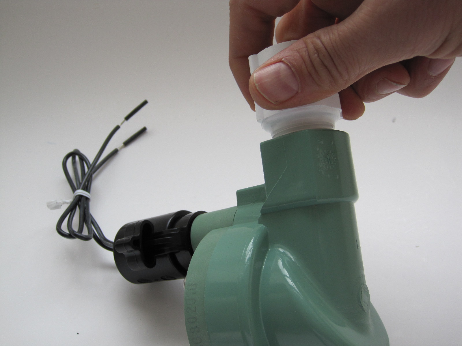
Find which of the two openings to the 3/4" inline 24V sprinkler valve is for the inflow. It is marked with arrows that point towards the valve, as shown below.

Prime and cement the 3" long 3/4" PVC pipe into the inflow side of the 3/4" inline 24V sprinkler valve, as shown below.

Prime and cement the 3/4" spig x 1/2" slip reducer bushing into the outflow side of the 3/4" inline 24V sprinkler valve, as shown below.

Now prime and cement the 16" long 1/2" PVC pipe into the 3/4" spig x 1/2" slip reducer bushing, as shown below.

Find the 2" spig x 3/4" slip reducer bushing. It's the part being held in the photo below.

Prime and cement the 2" spig x 3/4" slip reducer bushing into the 2" tee, slip x slip x slip, as shown below.
Prime and cement the completed launch system into the pressure chamber, as shown below.

STEP 3. BUILD THE LAUNCH STAND
Materials for step 3:
Two 16" long 3/4" PVC pipes
Two 14" zip ties
Tools for step 3:
Pencil
Measuring tape
Drill with bits: 5/16" and 3/16"
Small screwdriver
Instructions:
Find the parts shown below.

Mark the first piece 6-1/2" from one end.

Then mark it 6-1/2" from the other end.

Repeat the process for the second 16" long 3/4" PVC pipe. Using the 5/16" drill bit, drill a hole through the top of the PVC pipe at each of the marks that you made.
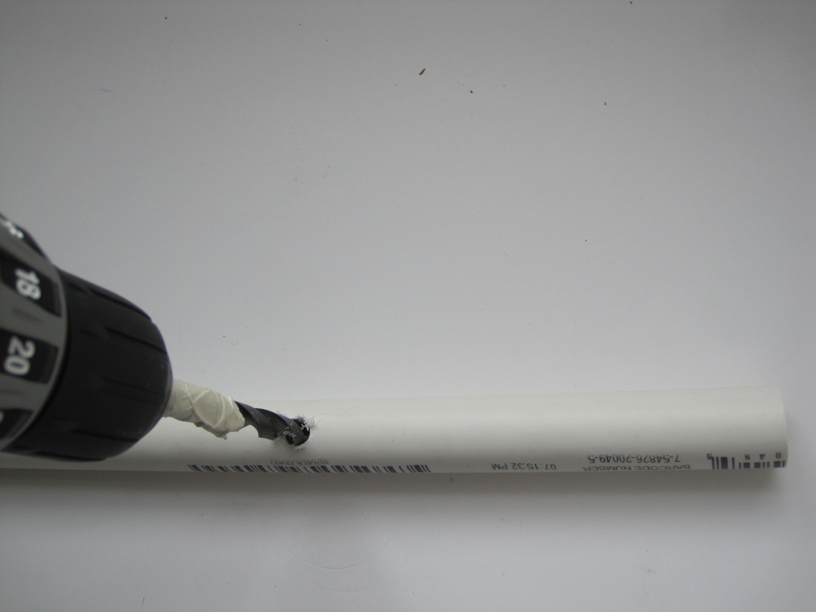
Stick the 3/16" drill bit in the middle of each of the holes that you just drilled and drill a hole through the bottom of the 16" long 3/4" PVC pipe, as shown below.

The hole should go all the way through the pipe.

When you are done, the top of each PVC pipe should look like
this:

And the bottom should look like this.

Thread the 14" zip tie through the large top hole of one of the 3/4" PVC pipes.

Poke a small screwdriver in the small hole in the bottom of the PVC pipe to help push the zip tie back up through the second large hole in the pipe.

Then pull it through the large hole.

Repeat these steps for the second PVC pipe.

STEP 4. MAKE THE LAUNCH CONTROLLER
Materials for step 4:
Two 3/4" caps, slip
One 3/4" PVC pipe, 4" length
One SPST momentary pushbutton switch (normally open)
One 22 AVG red/black zip cord, 10' length
Tools for step 4:
Block of wood for drilling
Vice grips
Drill with bits: 3/8" and 5/32"
Needle nose pliers
Instructions:
Find the parts shown below.

Support the 3/4" cap on a block of wood and hold it with a pair of vice grips. Using the 3/8" drill bit, drill a hole in the center of the cap.

Using the 5/32" drill bit, drill a hole in the center of the second cap.

To build the launch controls, you will need the following parts:

Strip the ends of the 10' long 22 AWG 22 red/black zip cord.

Take the end cap with the smaller hole, and insert the red/black zip cord through it from the outside of the cap.

Tie a knot about 8" from the end of the red/black zip cord.

Next, thread the wire through the 4" long 3/4" PVC pipe.
Next, take the nut and washer off the SPST momentary switch.

Thread the red/black zip cord through the nut and then the washer.

Thread the wire through the other end cap i.e. the one with the larger hole, from the inside.

We need to solder the red/black zip cord to the solder lugs on the SPST momentary switch.

Now solder them.
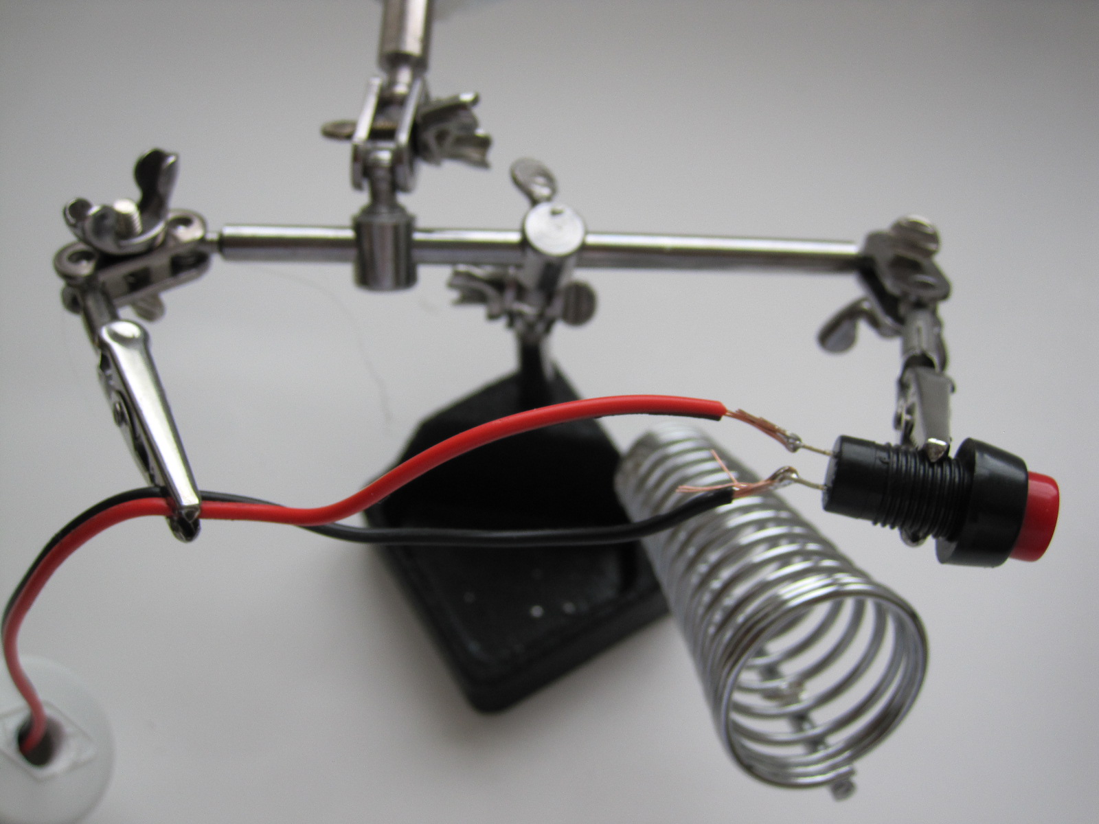
Wrap one or both of the leads with electrical tape.

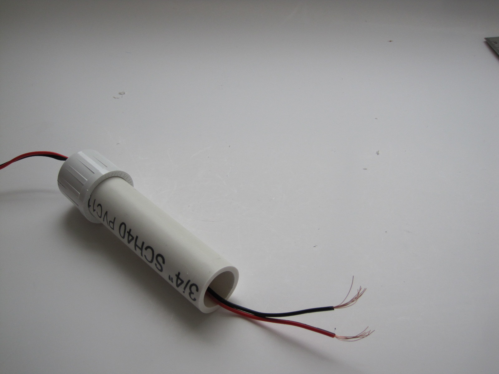
Insert the switch in the hole in the end cap.

Using needle nose pliers, try to tighten the nut for the switch.

The finished launch controller.

STEP 5. WIRE THE LAUNCH CONTROLLER
Materials for step 5:
Two 9V battery connectors, I-type
Two 9V batteries
Two 11" zip ties
Tools for step 5:
Electrical tape
Wire strippers
Soldering station plus solder
Instructions:
Using electrical tape, tape two 9V batteries together, as shown below.

Clip the two 9V battery connectors onto the batteries.

Strip the leads if needed. Twist together the negative lead from one of the batteries with the positive lead from the other battery.
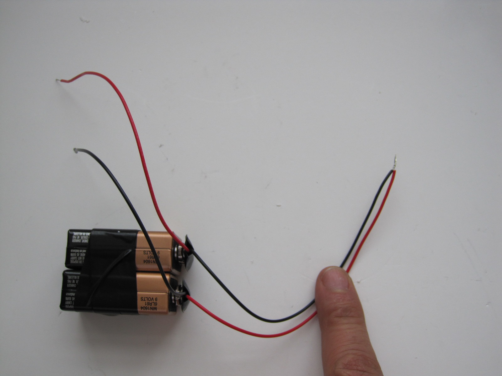
Solder the twisted leads.

Using electrical tape, tape the soldered connection.

Use one 11" zip tie to attach the batteries to the 3/4" PVC pipe that connects to the pressure chamber.

Strip the ends of the red.black zip cord.

Twist together one of the red/black zip cord wires with a lead from the sprinkler valve.

Twist together the other red/black zip cord wire and a lead from the batteries .

Twist together the remaining lead from the battery with the remaining lead from the sprinkler valve.
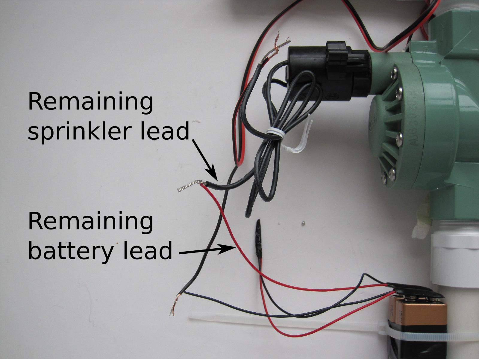
Solder all the connections and then tape them with electrical tape.

Using electrical tape or an 11" zip tie, attach the wires to the tube that runs between the pressure chamber and the sprinkler valve.

STEP 6. MAKE THE AIR HOSE AND FINAL ASSEMBLY
Materials for step 6:
One tire valve (Schrader valve)
One 5/16" OD x 3/16" ID flex. tubing, 6' [McMaster Carr part 53945K126, $5.64 ]
Two pinch hose clamps, 9/32" to 23/64" [McMaster Carr part 6541K35, $8.00 for 25]
Tools for step 6:
Pinch clamp pincer
Duct tape
Instructions:
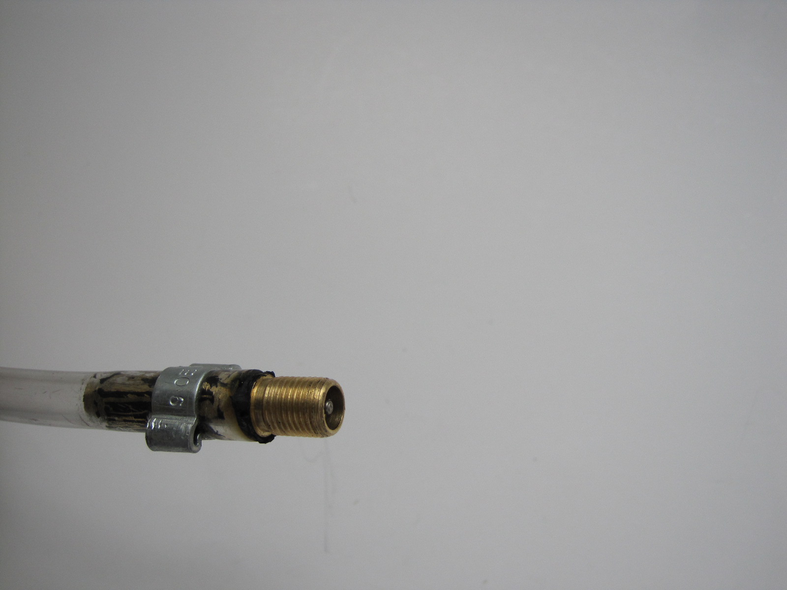
Strip the rubber off the tire valve. You can use a Dremmel or end nippers. Slip a hose clamps over the flexible tubing. Insert the tire valve into the tubing and pinch the ears of the clamp with a pinch clamp pincer.
Slip another hose clamp over the other end of the flexible tubing. Push the tubing onto the barb on the outside of the pressure chamber. Pinch the ears of the clamp with a pinch clamp pincer.

Wrap duct tape all around the pressure chamber.

Place the pressure chamber on the stand made from two 3/4" PVC pipe and connect the two 14" zip ties.

Congratulations! You're done!
Link for rocket building instructions.