

This is a creative and easy-to-make robotic vehicle created by the instructors at http://www.teachmetomake.com/. It will be your introduction to basic soldering. You can buy a kit at http://www.makershed.com/ for $15 or you can buy the parts on your own.
Materials (for each kid):
2 AA batteries
5 large craft sticks
2 clothespins
1 straightened large paperclip or 4" piece of 18 AWG wire (stripped)
1 piece of foam core (2.5" x 5")
2 DC toy motors, 1.5 - 3 volts [Hobby Engineering part H02242-01Z, $1.99 ea.]
1 battery holder, AA [All Electronics part BH-32, $0.75 ea.]
1 white 22 AWG stranded wire, 6' [All Electronics part 22WT-25, $2.10 for 25']
1 red 22 AWG stranded wire, 6' [All Electronics part 22RD-25, $2.10 for 25']
1 black 22 AWG stranded wire 6' [All Electronics part 22BK-25, $2.10 for 25']
2 black 22 AWG stranded wire, 6" ea. [All Electronics part 22BK-25, $2.10 for 25']
2 pieces screening spline, 1" ea. [McMaster-Carr part 1087A23, $2.03 for 15']
8 zip ties, 4" long
Tools (for each kid):
Soldering station
Helping Hand with magnifier
Safety goggles
Test lead, with alligator clips at each end
Magazine (or book)
Tools shared by kids in two person teams:
Glue gun
Tools shared by two or three teams at a table:
1 automatic wire strippers
1 wire cutters
1 scissors
1 pliers (optional)
Step 1:
In step 1, we will build the vehicle's chassis and attach the motors.
The little metal tabs on the motor are called "solder lugs". When you buy parts for soldering make sure they have solder lugs. Gently bend the solder slug tabs up. This will give you more room to solder. Do not bend them back and forth or they will break off.


First, you need to solder together the three black wires that you twisted together earlier. Use your Helping Hand to hold the three twisted wires in place for soldering, as shown in the photo below. Notice how all three wires run in the same direction.


Soldering station
Helping Hand with magnifier
Safety goggles
Test lead, with alligator clips at each end
Magazine (or book)
Tools shared by kids in two person teams:
Glue gun
Tools shared by two or three teams at a table:
1 automatic wire strippers
1 wire cutters
1 scissors
1 pliers (optional)
Step 1:
In step 1, we will build the vehicle's chassis and attach the motors.
The little metal tabs on the motor are called "solder lugs". When you buy parts for soldering make sure they have solder lugs. Gently bend the solder slug tabs up. This will give you more room to solder. Do not bend them back and forth or they will break off.

Before gluing, you need to position the motors on the craft stick. You want the axles to touch the floor but not the motor bodies. The tricky part is that you also need the motors to be on as much of an angle as possible. This is explained below. You can use a magazine (or book) to help you position the motors properly. Place the craft stick on top of the magazine, and then align it on the front edge of the magazine, as shown below.

Now place the motors on the table. Here are two things you need to do to get the correct positioning:
- tilt the motors inward as far as possible so the axles touch the binding but the motor bodies do not (as shown below). This will be about a 45˚ angle.
- line up the bottom corners of the motors with the outside edge of the craft sticks. This is shown by the red line in the photo below. See how the two circled areas in the photo are aligned on the red line?

Now gently put your craft stick on top of the motors to make sure it all looks good. The bottom edge of the craft stick should be aligned with the bottom corner of the motor,as shown below.

If it looks good, gently pick up the craft stick and glue it to the motors. Make sure you push down on the craft stick to set the glue, as shown below..

Flip the part you just glued on its back, as shown in the photo below.

Glue the second craft stick on top of the motors, as shown below.

Now glue a craft stick at each end of the two craft sticks you just glued, as shown below.
[photo to follow].
Flip the vehicle over and add more glue as shown below.

Then glue a craft stick on the back, as shown below.

Finally, flip your vehicle over and make sure that it all looks good; only the axles and the back craft stick should be touching the ground. The photo below shows how it should look.

Step 2:
In step 2, we will connect wires to the motors.
Strip about 1/2" off the end of your 6' red 22 AWG stranded wire. If the wire strippers break the wire strands, use a lower gauge. I find that wire strippers strip 22 AWG stranded wire better using the 20 AWG setting. After you strip the wires, twist the exposed strands of metal wire, as shown below.

Bend the stripped part of the wire in the middle and then feed the bent wire through the OUTSIDE solder lug of one motor. After you feed it through, pinch the stripped part of the wire so the wire looks like the wire in the photo below. See how the pinched part of the wire folds back on itself? You can hardly tell it's looped. This will make soldering easier.

You are now ready to solder the wire to the motor, so put your goggles on. You should always wear goggles when you solder because solder can easily pop off and hit you in the eye.

After your goggles are on, solder the wire to the motor. Notice three things in the photo below:
- The solder, the soldering iron and the 22 AWG stranded wire are all touching each other.
- The soldering iron is not near the wire's nylon casing
- The soldering iron is positioned so that a point slightly below its tip is making contact; the tip isn't touching anything. This is because the tip of the soldering iron is not the hottest part.

Now we will solder the 6' white 22 AWG stranded wire to the other motor. Strip, twist and bend the wire as you did the red wire earlier. Then feed it through the OUTSIDE solder lug of the other motor, pinch and solder it as before with the red wire. This is shown in the photo below.

By connecting the 6' white 22 AWG stranded wire to the outside lug on this motor, you are actually soldering it to the opposite lug of the first motor. This means that the motor will spin in the opposite direction of first motor.
Now, you need to connect the two 6" black 22 AWG stranded wires (i.e. the short black wires) to the INSIDE solder lugs of the motors. That means each motor will have a long red or white wire and a short black wire connected to it, as shown in the photo below.

Step 3:
In step 3, we will check the motors to make sure they still work and that you didn't damage them during soldering.
Put two AA batteries in your battery holder. Take your first set of test leads and clip them to the red wire on the battery holder. Then take you second set of test leads and clip them to the black wire on the battery holder. This is shown in the photo below.

Now, strip 1/2" off the end of the 6' black 22 AWG stranded wire (i.e. the LONG black wire) and twist it around the ends of the two 6" 22 AWG stranded wires (i.e. the short black wires), as shown in the photo below.

Now, connect the twisted section of the three black wires to the black wire on your battery holder using a test lead. Then take the other test lead (i.e. the one that's clipped to the red wire on the battery holder) and touch it to the solder lug that the red 22 AWG wire is soldered to. The motor should run. See the photo below.

Then, test the other motor - touch the same test lead to the the solder lug that the white 22 AWG wire is soldered to. That motor should run as well. If one other motors, didn't work you will need to troubleshoot the problem.

Then, test the other motor - touch the same test lead to the the solder lug that the white 22 AWG wire is soldered to. That motor should run as well. If one other motors, didn't work you will need to troubleshoot the problem.
Step 4
In step 4, we will attach the wires to the chassis and run them to the remote control.

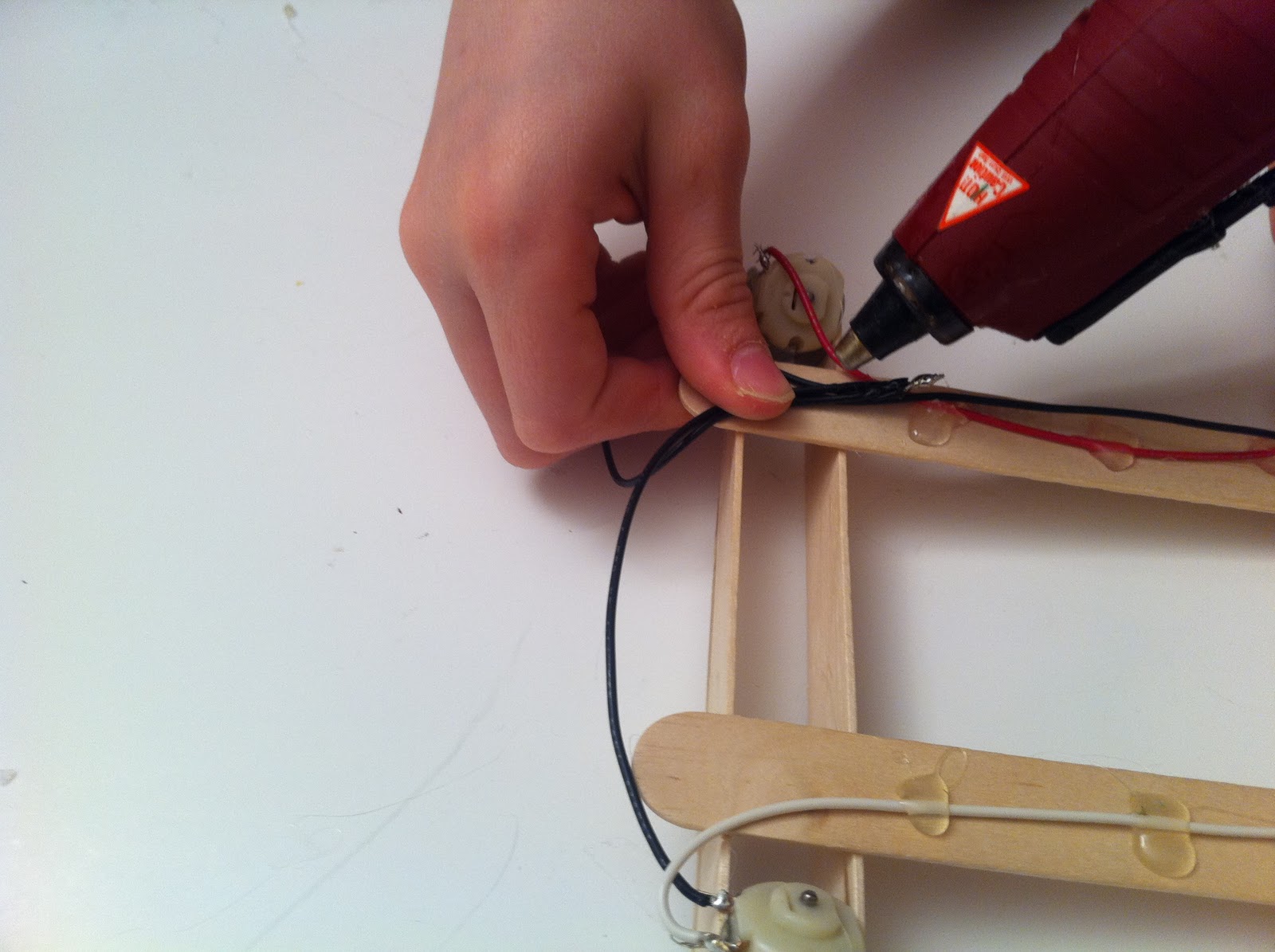
Now glue all the red and white wires to the craft sticks. Make sure the glue dries with the wire pressed against the craft stick. The best way to do this is to press with your fingers on each side of the glued area, as shown in the photo below.

The black wires are a little tricky to glue. Before gluing them, fold them together on one side of the craft stick, as shown in the photo below.
After gluing all the wires, put a zip tie at the back of the vehicle, connecting all the wires. Make sure the zip tie is closed tightly against the craft stick and then trim it, as shown in the photo below.

Now put zip ties on the three 6' wires every 18" or so. Don't zip tie the last foot or so of wire. If you are having a hard time tightening the zip ties, try using pliers to pull them closed.
Place the screening spline on each axle and trim it so it is about 1/8" past the end of the axle.

Step 5
In step 5, we will build the remote control and connect the wires to it.
First, we need to figure out how to connect the wires the batteries so the vehicle moves forward instead of backward.
Strip about 2" - 3" off the end of the red and white wires (but not the black wires). That's about the length of your pinky finger, as shown in the photo below.
Now, it's time to make the remote. Glue the two clothespins to the foam core board. The board is longer than the clothespins. Leave the excess part of the board at the back of the clothespins, as shown below.

IT IS VERY IMPORTANT THAT YOU DO THE FOLLOWING CORRECTLY:
- Face the foam core board so that the pinching ends of the clothespins face away from you.
- Wrap the wire that runs to the vehicle's RIGHT motor around the end of the handle of the LEFT clothespin.
- Wrap the wire that runs to the vehicle's LEFT motor around the end of the handle of the RIGHT clothespin. Make sure you wrap them tightly.
- Glue the wires to the tops of the clothespins.

Now you need to connect the 6' black 22 AWG wire. To do this take the paperclip or 18 AWG wire and bend it in a U so that it fits under the clothespin handles. DO NOT GLUE IT YET. THE PHOTO BELOW SHOWS HOW TO BEND IT, NOT HOW TO GLUE IT. If the paperclip is too long, trim it with wire clippers.

Next glue the battery pack on the bottom of the foam core board, as shown in the photo below.

Now, you need to figure out how to run the wires to make your vehicle run forward, instead of in reverse. To do this, strip 1/2" off the unstripped end of the 6' black 22 AWG wire. Now connect the newly stripped part to the test lead that's conected to the black wire of your battery holder.
Then take the test leads that's connected to the red wire of your battery holder and touch it to the stripped section of the red wire on your clothespin. The motor that the red wire runs to should move forward. Then do the same for the white wire and the other motor should move forward. If it goes in reverse, switch the connections to the batteries--that is switch the battery holder wires. If it doesn't move at all, troubleshoot your connections.
Now it's time to solder the wires in place to make the connections permanent instead of using test leads. First let's connect the 6' black AWG wire. Unclip the test lead and solder the 6' black AWG to the same wire on the battery holder that it was just connected to. In the photo below, the vehicle went forward when the 6' black 22 AWG wire was connected to the red battery holder wire. The photo below shows it being soldered in place.

Now solder the other wire of the battery holder to the paperclip, as shown in the photo below.

Glue the paperclip (or 18 AWG wire, if that is what you used) in place on the foam core board. Make sure the stripped parts of the red and white 22 AWG wires make contact with the paperclip (or 18 AWG wire) when you push the clothespins, as shown in the photo below.

Then glue any loose wires on the bottom of the foam core board, as shown below.

You're done. Enjoy!
No comments:
Post a Comment