More About The Bridge Rectifier
When the magnet changes direction in the tube the direction of the current reverses. That type of current is called alternating current (AC). That's a problem for LEDs because LEDs are diodes. As you know (I hope), a diode is a semiconductor that conducts electric current in only one direction, from positive to negative. The diagram below shows this.
Diodes only work when their anode is hooked up to positive current and their cathode is hooked up to a negative current. That means they work only on direct current (DC)--that is, current that does not change directions. The kinetic flashlight uses another type of diode, called a Schottky diode to fix the problem and convert AC current to DC current that our LED can use.
In the diagrams to the right, the blue wires run to the coil of magnet wire. That's were the electric current is generated, but it's alternating current (AC). The green wires in the diagram run to the LED. The current in the top green wire (i.e. the one marked "+" in the diagram) runs to the LED's anode and the current in the bottom green wire (i.e. the one marked "-" in the diagram) runs to the LED's cathode. Now, can you figure out how the current coming in through the blue wires flows?
First assume the current coming in through top blue wire is positive and the current in the other blue wire is negative. (This is shown in the top diagram to the right.) See how the positive current flows to the top green wire and the negative current flows to the bottom green wire?
Now assume the current in the blue wires is reversed, and that the positive current is coming through the bottom blue wire. See how the positive current flows still flows to the top green wire and the negative current still flows to the bottom green wire? So no matter which way the magnets move, the diodes always divert the current's flow to the same points on the green wires.
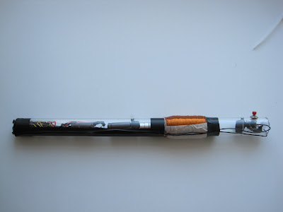
If you look at he breadboard pictures of the kinetic flashlight, you will notice that the diodes on the breadboard match the diagram above.
More About the Voltage Regulator
The voltage regulator takes fluctuating voltage created by the shaking magnets and smoothes it out to a consistent 3.3V (or thereabout). The voltage regulator has three pins. You will also notice that one side of the plastic on the voltage regulator is flat. Face the flat side towards you. Pin 1 is on the left, pin 2 is in the middle and pin 3 is on the right.
What do the pins mean? Well, it's pretty simple. When you wire a voltage regulator, you'll end up with two sub-circuits. One sub-circuit will be before the voltage is regulated, and it will have a positive and negative connection like all circuits. The second sub-circuit will be after the voltage is regulated. It too will have a positive and negative connection. So, if you think about it, the voltage regulator should have four connections: positive and negative for the sub-circuit with unregulated voltage (i.e. fluctuating voltage) and positive and negative for the sub-circuit with regulated voltage (i.e. smooth voltage). But, if you look at our voltage regulator, there are only three pins. That's because the unregulated and regulated sub-circuits both use one pin for their negative connections. That's pin 2. So, pin 1 is the connection for the positive unregulated sub-circuit. Pin 3 is the connection for the positive regulated sub-circuit. And, pin 2 is the connection for both the unregulated and regulated negative sub-circuits.
Looking back at our kinetic flashlight, let's review the components in each sub-circuit. In the unregulated sub-circuit, you will have the bridge rectifier and the capacitors. In your regulated sub-circuit, you will have the SPST momentary push button switch and the LED.


No comments:
Post a Comment